← All Antenna examples
ANTENNA FDTD STUDIO · APPLICATION EXAMPLE

Parabolic Reflector

A parabolic reflector with an illuminating horn. Explore the original model, recorded electromagnetic fields, radiation patterns and frequency response.

01 · MODEL SETUP

Inside the application.
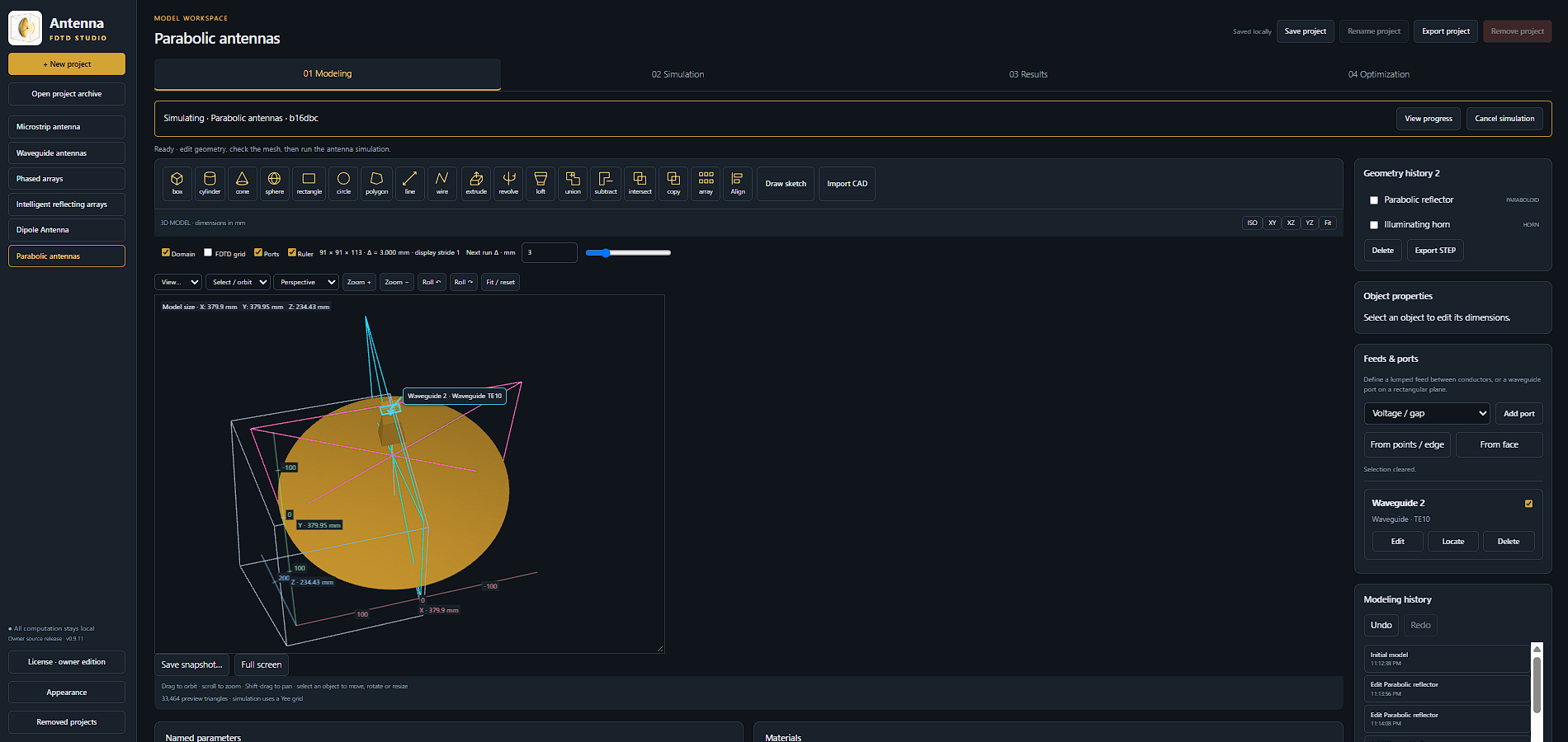
The supplied Antenna FDTD Studio modeling workspace, showing the parabolic reflector, illuminating horn and Waveguide TE10 port.
Parabolic reflector workspaceThe supplied Antenna FDTD Studio modeling workspace, showing the parabolic reflector, illuminating horn and Waveguide TE10 port.
02 · RECORDED FIELDS

Follow the field around the reflector.

Recorded electromagnetic-field animation · all 24 exported frames, in their original order and at the original 12 fps playback rate.

03 · RADIATION PATTERNS

See the radiated response.
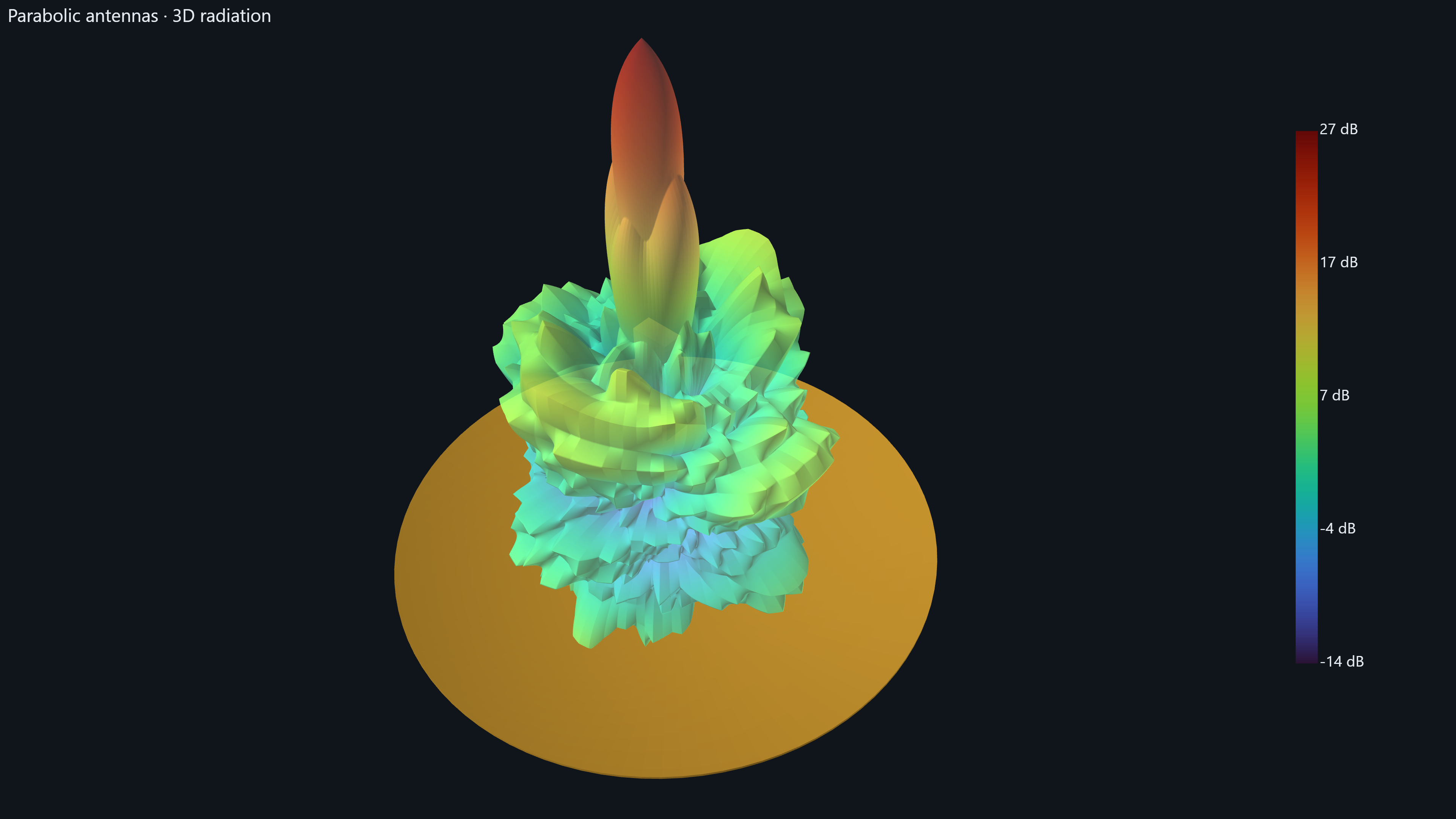
The supplied 3D radiation view around the parabolic reflector, retaining the original color scale.
3D radiation patternThe supplied 3D radiation view around the parabolic reflector, retaining the original color scale.
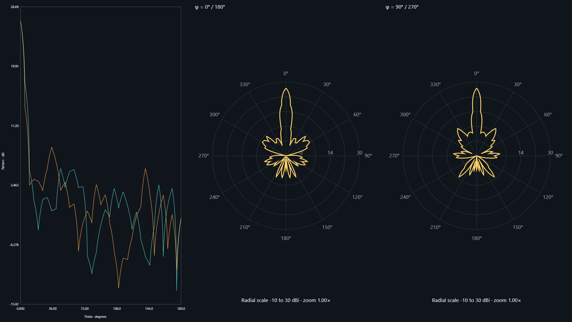
Pattern versus theta, alongside the φ = 0° / 180° and φ = 90° / 270° polar cuts. The supplied polar plots retain their −10 to 30 dBi radial scales.
Radiation cutsPattern versus theta, alongside the φ = 0° / 180° and φ = 90° / 270° polar cuts. The supplied polar plots retain their −10 to 30 dBi radial scales.
04 · PORT RESPONSE

Return loss and matching.
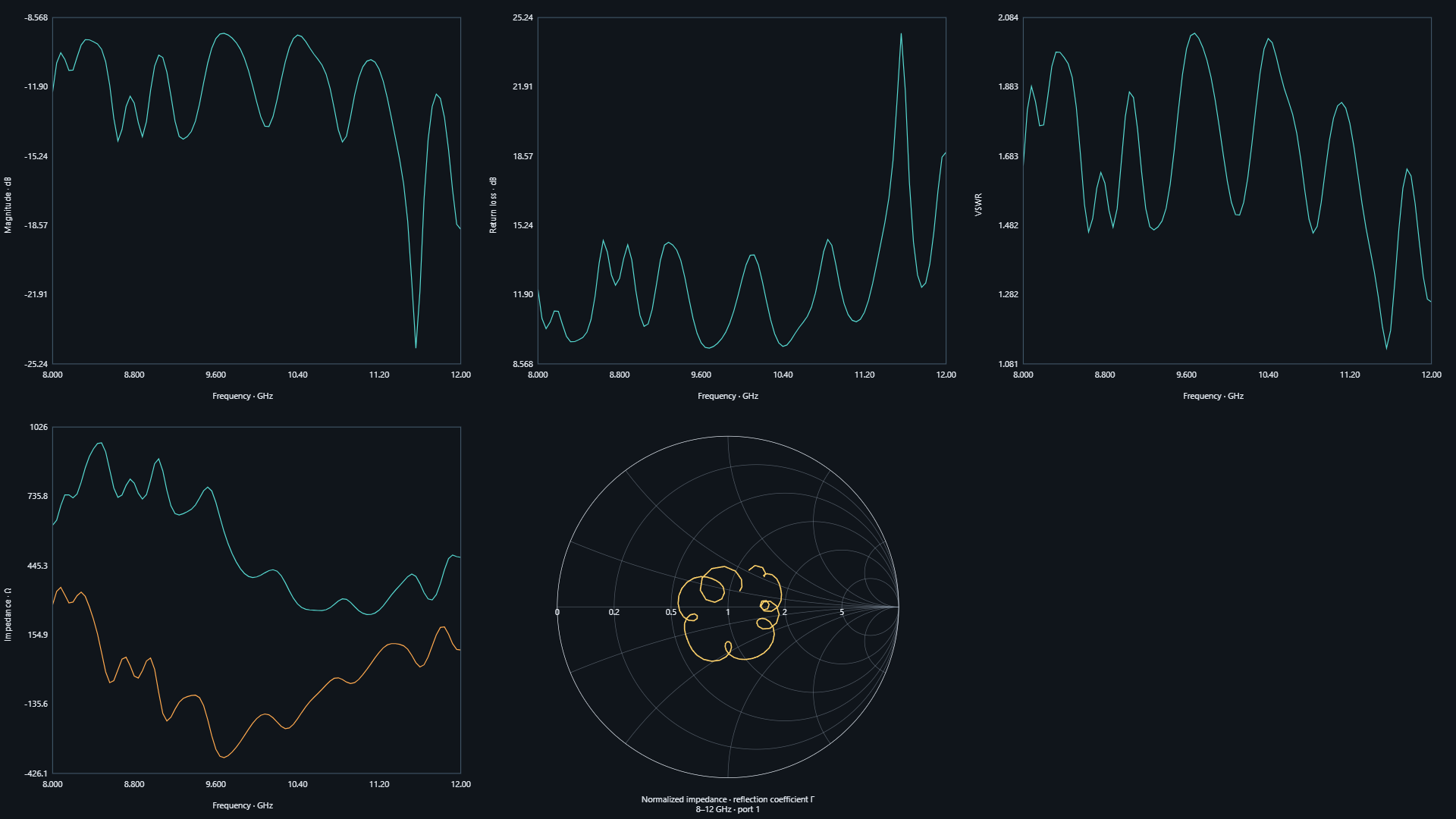
The supplied magnitude, return-loss, VSWR and impedance plots, together with the port 1 Smith chart. Original axes, curves and labels are preserved.
Frequency response · 8–12 GHzThe supplied magnitude, return-loss, VSWR and impedance plots, together with the port 1 Smith chart. Original axes, curves and labels are preserved.

Images retain the supplied plots, axes and color scales. The video is a web-playback copy of the exported animation, preserving its frame count, dimensions and timing. These are recorded simulation results; this page does not run a solver.

Back to Antenna examples