← All Antenna scenarios
ANTENNA FDTD STUDIO · APPLICATION SCENARIO

Microstrip antenna.

A patch antenna, its coax-gap feed, and the recorded electromagnetic response. Explore the original modeling workspace and exported results below.

01 · MODEL SETUP

Inside the application.
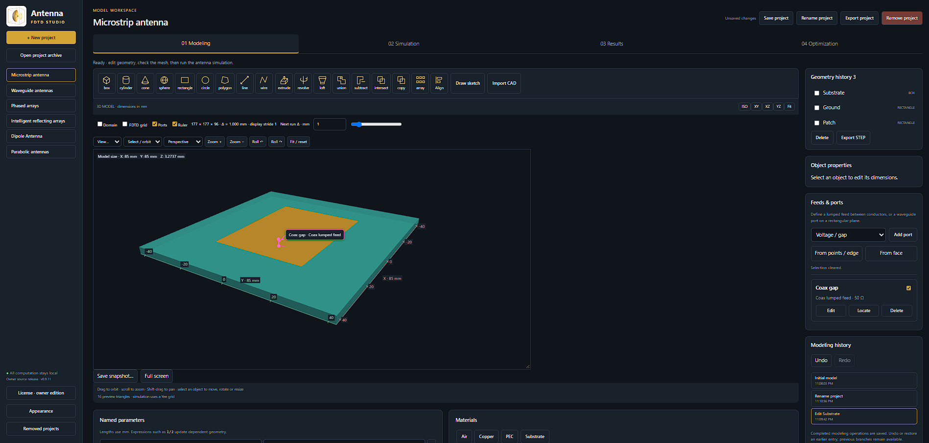
The microstrip antenna in the Antenna FDTD Studio modeling workspace, showing the substrate, ground, patch and coax-gap lumped feed.
Patch, substrate and feedThe microstrip antenna in the Antenna FDTD Studio modeling workspace, showing the substrate, ground, patch and coax-gap lumped feed.
02 · RECORDED FIELDS

Follow the field response.

Recorded field animation · the supplied field sections, color scale and frame timing, with no change to the playback speed.

03 · FREQUENCY RESPONSE

Matching and impedance.
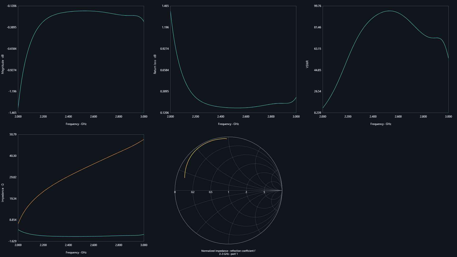
The exported magnitude, return loss, VSWR, impedance and Smith-chart views, retaining the original frequency axes and plotted traces.
Port response across frequencyThe exported magnitude, return loss, VSWR, impedance and Smith-chart views, retaining the original frequency axes and plotted traces.
04 · RADIATION PATTERNS

Explore the spatial response.
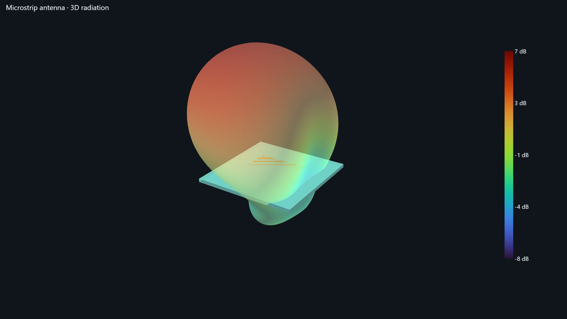
The original 3D radiation view around the microstrip antenna, retaining its supplied color scale.
Three-dimensional radiation patternThe original 3D radiation view around the microstrip antenna, retaining its supplied color scale.
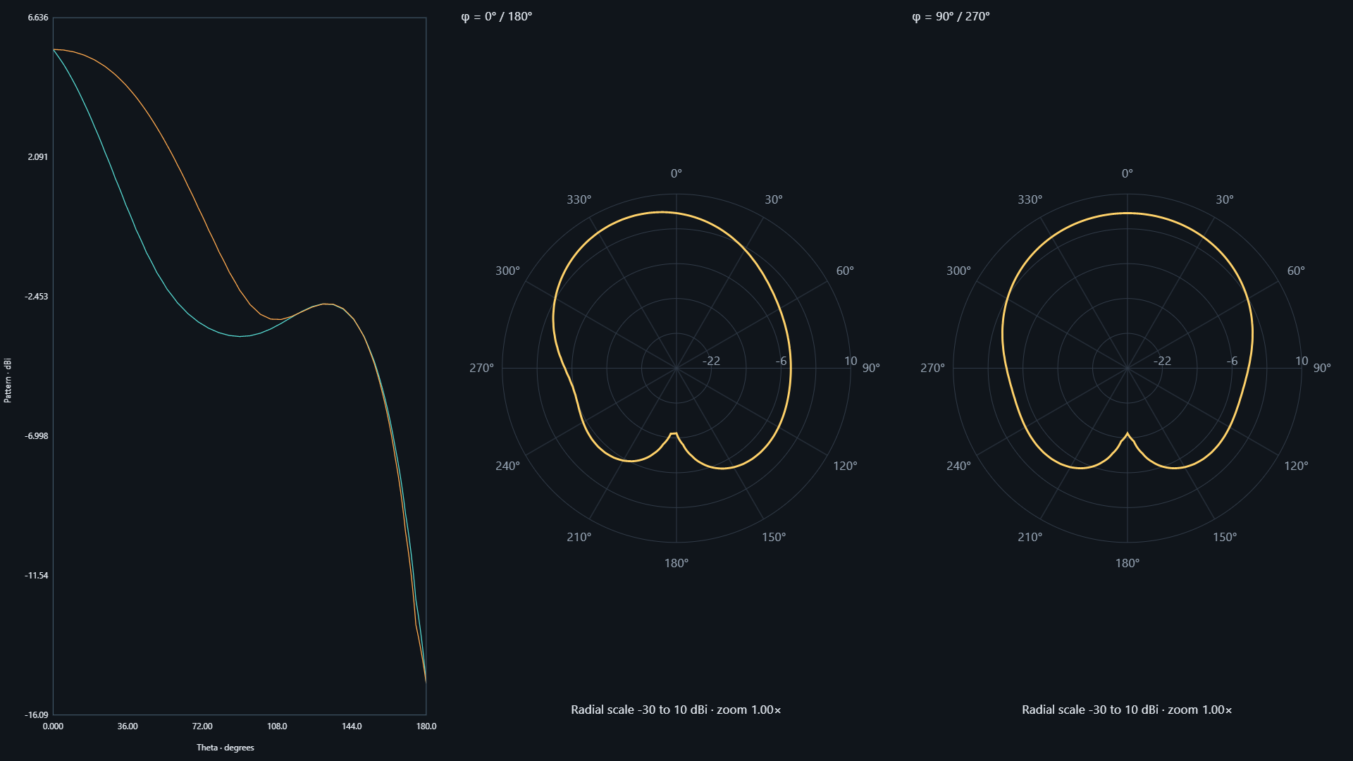
The supplied pattern-versus-theta plot and polar cuts at φ = 0° / 180° and φ = 90° / 270°, with their original angular axes and dBi scales.
Radiation-pattern cutsThe supplied pattern-versus-theta plot and polar cuts at φ = 0° / 180° and φ = 90° / 270°, with their original angular axes and dBi scales.

Images retain the supplied plots, axes and color scales. The video is a web-playback copy of the exported animation. These are recorded simulation results; this page does not run a solver.

Back to Antenna scenarios